How the Electric Generator Works Step by Step Explained
Electric generator works in three steps that include; fuel combustion, thermo-mechanical conversion and electromagnetic induction.
This article discusses how an electric generator works in steps, as follows;
1). Fuel Combustion (in explanation of How the Electric Generator Works)
The first stage in the operation of an electric generator is combustion of fuel.
For fuel to be combusted, it must first be introduced into the generator through the fuel feeder component.
It must be noted that fuel combustion in the electric generator is equivalent to a conversion of chemical energy to thermal energy. Chemical energy is stored in the fuel which is burnt under controlled conditions to release heat.
Generators can be classified based on the fuel which they use. Types of generators based on fuel include natural gas, gasoline, and biomass generators.
Combustion in a generator works by a simple mechanism of air injection, fluid mixing and spark ignition. This mechanism is based on principles collectively known as the Otto Cycle; which exploits the relationship between temperature, pressure and volume of fluids to achieve a highly-controlled form of combustion where fluid is heated so that it expands and exerts pressure on a rotary component of the generator [4].
The internal combustion engine (ICE) of a generator is equipped with a combustion chamber into which fuel from the fuel-feeder is injected alongside controlled volumes of air. As these fluids are injected and compressed, they become pressurized, so that they can be easily ignited by the spark plug, which is connected to the chamber.
The products of combustion are released through the exhaust of the generator.
Fuel combustion is the cause of greenhouse emissions and air pollution by electric generators.
Gases that can be emitted by an electric generator include carbon monoxide (CO), carbon dioxide (CO2), nitrogen oxide (NOx), and sulfur dioxide (SO2) [5].
Particulate matter, especially in the form of carbon soot, may also be emitted in some cases.
The energy efficiency of the combustion engine is an important metric that determines the performance of an electric generator. It refers to the amount of useful energy that is produced per unit volume of fuel that is burnt.
Energy efficiency of ICE engines in generators and vehicles ranges from 11 - 37% [2].
In order to mitigate the environmental impact of fuel combustion in electric generators, efforts are being made to improve engine efficiency, as well as to make innovative inputs like the integration of carbon capture equipment with large generators and power plants.
2). Thermo-Mechanical Conversion
After fuel combustion has occurred, the next step in the electricity generation process is thermo-mechanical conversion; which entails the transformation of heat from the combustion chamber to mechanical energy that mobilizes a movable component.
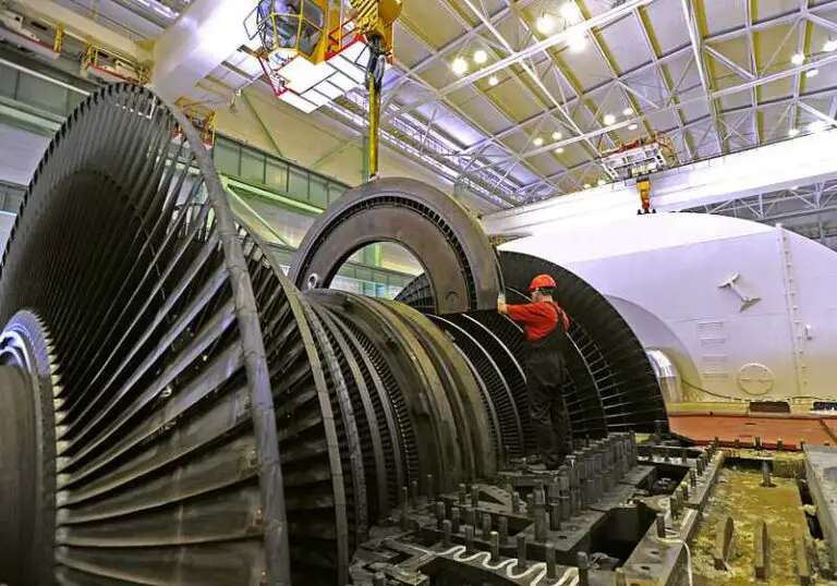
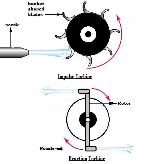
The movable component in an electric generator usually occurs in form of a rotary turbine or similar structure, that is connected to a shaft.
It is important to state that the principle of mechanical energy production from heat in an ICE generator is very similar to that used in other electricity generation systems, including renewable energy systems like wind turbines and wave energy converters.
In these systems, mechanical energy generally comes from the pressure exerted by a fluid (which could be steam, water, combustion gases, wind).
The moving component is usually equipped with blades or similar structures that provide a suitable surface area for collision with the fluid. In ICE generators, the fluid is heated gas from the combustion chamber which has gained significant pressure (in line with the Otto Cycle and its exploitation of P-V-T relationships) and has expanded due to heating.
In summary, heat energy can be converted to mechanical energy in an electric generator because of the direct proportionality of heat and pressure. Pressure that is gained due to high temperature is what causes the movable component(s) to rotate, thereby producing mechanical energy.
3). Electromagnetic Induction (in explanation of How the Electric Generator Works)
An electric generator generates electricity by converting mechanical energy to a stream of charges through a mobile conductor, in a process also known as electromagnetic induction [1].
Electromagnetic induction in generators is the process whereby current begins to flow through a conductor as a result of the effect of a magnetic field on electrons in the conductor as it moves continuously (usually by rotation) in the field.

The ability of generators to convert mechanical energy to electricity through electromagnetic induction, indicates the relationship between electric charges and magnetic fields, which is summarily addressed under the concept of electromagnetism.
Electromagnetism is used in an electric generator to induce an electromotive force (EMF) in a moving conductor, whose function is to mobilize electrons and cause them to flow through the conductor as it moves relative to a magnet.
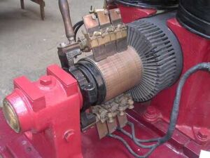
To better understand electromagnetic induction in an electric generator, it is helpful to identify the functions of some components that include; commutator, armature, slip rings rotor and stator.
The rotor and stator represent the two main parts of the electro-mechanical unit which is directly in charge of conveying mechanical energy to the magnetic field in a generator.
The rotor itself is the mobile component of this assembly, while the stator is the stationary component that is designed to conduct electricity away from the rotor in which it has been induced by electromagnetic induction.
Slip rings are circular components made from conductive material, whose purpose is to establish a connection between rotary and stationary conductors in the generator [3]. For example, slip rings can be used to conduct electricity from the rotor to the stator.
A stationary and rotary slip ring respectively are usually needed to establish such connection, so that the stationary ring is linked to a stationary component and is in continuous contact with the rotary slip ring, which is connected to a rotating component.
The arrangement ensures that there are few moving parts in the generator, and helps to optimize energy efficiency by minimizing losses through friction.
Commutator is similar to a slip ring, but differs by being segmented or having gaps along its circumference, while the slip ring is continuous.
The role of the commutator is to continuously reverse the magnetic poles of the rotating conductor as is moves in the magnetic field, so that the rotation of this conductor is uniform or synchronous with the reversal of the field.
This polar reversal causes the direction of the current that flows through the conductor to alternate, and produces what is known as Alternating Current (AC), which then flows through the conductor.
The commutator performs similar function to a power inverter that is used to convert DC from electricity generation systems to AC. It must be noted that DC-AC conversion is essential because electrical appliances generally require alternating current (AC) to operate.
Armature refers to the part of a generator which is used solely to conduct alternating current that has been generated, and to convey this current from the generator to the load.
The armature may occur in form of copper wire that is wound around the rotor, especially in small-scale generators. It must also be noted that the magnet is usually equipped with conductor wire called the field winding, that is wrapped around it. The electromagnetic interaction between armature and field windings is what produces the electromotive force (EMF) that causes electrons to flow through the armature.

In simple terms, EMF is induced in a generator when electrons are mobilized so that they flow through a conductor by virtue of the attraction-repulsion effect of an external magnetic field on their dipoles. This process is what is behind electromagnetic induction, and accounts for the generation of electricity in most generators.
Conclusion
How the electric generator work step by step is as follows;
1. Fuel Combustion
2. Thermo-Mechanical Conversion
3. Electromagnetic Induction
References
1). Al-Khalili, J. (2015). "The birth of the electric machines: A commentary on Faraday (1832) 'Experimental researches in electricity'." Philosophical Transactions of The Royal Society A Mathematical Physical and Engineering Sciences 373(2039). Available at: https://doi.org/10.1098/rsta.2014.0208. (Accessed 15 February 2023).
2). Albatayneh, A. M.; Assaf, M. N.; Alterman, D.; Jaradat, M. (2020). "Comparison of the Overall Energy Efficiency for Internal Combustion Engine Vehicles and Electric Vehicles." Environmental and Climate Technologies 24(1):669-680. Available at: https://doi.org/10.2478/rtuect-2020-00. (Accessed 15 February 2023).
3). Botha, S.; Gule, N. (2022). "Design and Evaluation of a Laminated Three-Phase Rotary Transformer for DFIG Applications." Energies 15(11):4061. Available at: https://doi.org/10.3390/en15114061. (Accessed 15 February 2023).
4). Dahham, R. Y.; Wei, H.; Pan, J. (2022). "Improving Thermal Efficiency of Internal Combustion Engines: Recent Progress and Remaining Challenges." Energies, MDPI, vol. 15(17), pages 1-60. Available at: https://ideas.repec.org/a/gam/jeners/v15y2022i17p6222-d898585.html. (Accessed 15 February 2023).
5). Oriakpono, O. E.; Ohabuike, U. C. (2022). "Determination and Comparison of CO2 and Air Pollutants Emitted From the Exhaust Gas of Selected Electric Generators." Sultan Qaboos University Journal for Science [SQUJS] 27(1):1-18. Available at: https://doi.org/10.53539/squjs.vol27iss1pp1-18. (Accessed 15 February 2023).