Gas Turbine Working Principle Explained
Gas turbine working principle is the principle of the Brayton Cycle and comprises of four processes that include air-fuel mixing, isobaric combustion, mechanical energy production, and fluid exhaustion [7].
This article discusses gas turbine working principle, as follows;
1). Air-Fuel Mixing (as a Component of the Gas Turbine Working Principle)
Air-fuel mixing signifies the onset of gas turbine cycles of operation.
The fuel used in gas turbines is mostly natural gas, which is preferred because of its gaseous phase and ease of mixing with air, as well as due to its efficiency and high energy density.
For gas turbines, the correct ratio of air-fuel mixture is not a fixed, standard value, but varies according to factors like turbine design, size, fuel composition, and intended performance/mode of operation..
The ratio used in gas turbines for mixing air and fuel ranges from less than 10:1, to about 140:1 on average. Some gas turbines can work with an air-fuel ratio of up to 200:1.
It has already been stated that air-fuel mixing ratio affects gas turbine efficiency and performance.
The effect of high air-fuel ratio in a gas turbine is a general increase in internal fluid pressure, and a decrease in net energy yield. This is because larger volume of air reduces the relative amount of fuel while increasing the entropy of the combustion system, so that combustion efficiency becomes low.
Excessively high air-fuel ratio is only recommendable where the fuel has an equally high energy density, and where the combustion cylinder is designed to handle high gas pressure.
Air-fuel mixing occurs as a result of functions like air intake and compression, which occur in the combustion chamber of the gas turbine.
The energy efficiency of the process of air-fuel mixture in gas turbines, depends on environmental factors like pressure and temperature of the system [3].

2). Isobaric Combustion
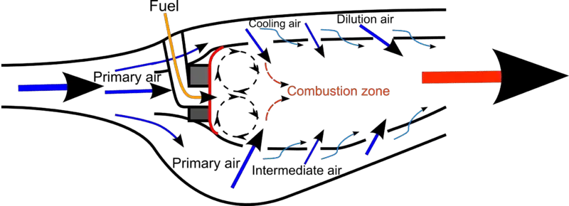
Combustion in gas turbines is the controlled burning of the air-fuel mixture in the combustion chamber of the system.
Gas turbines depend on the presence of oxygenated fuel for their combustion, along with suitable temperature and pressure conditions.
Types of combustion systems in gas turbines are; tubular and annular types, which are classified based on design and operation. There are also two types of combustion in gas turbines, which are; premixed and diffusion combustion [4].
The steps involved in gas turbine combustion process are; ignition, fuel decomposition and thermal energy production.
Combustion in gas turbines is called isobaric, because it is described as a constant-pressure process. However, this is an idealization.
In real-life scenarios, pressure is not constant during the combustion and air-fuel mixture in gas turbines. This is because of the increase in temperature of the heated fluid mixture, which simultaneously raises the pressure of the fluid.
Gas turbine combustors are designed to manage their internal pressure through compression and expansion mechanisms.
3). Mechanical Energy Production (as a Component of the Gas Turbine Working Principle)
Mechanical energy is the main type of energy which a gas turbine produces, from the conversion of thermal energy released during fuel combustion.
The turbine produces mechanical through the interaction of impulsive kinetic forces of fluids on the movable parts of the turbine, such as the rotor blades.
It must be noted that as the heated working fluid collides with the blades of the turbine, it loses its thermal energy and pressure, and as a result it expands, with significant increase in volume. Controlling this expansion is part of the functions of compressors and exhaust components of the system.
Mechanical efficiency of a gas turbine is a measure of the degree of energy conservation that is achieved as thermal and kinetic energies of the working fluid are used to rotate the turbine and produce mechanical energy.
It is simply energy efficiency with specific regard to thermo-kinetic-to-mechanical conversion.
The mechanical efficiency of a gas turbine may range from less than 20% to approximately 40% in real-life scenarios, although theoretical and idealistic estimates may place the value at 60% and above.
A gas turbine produces electricity from the mechanical rotation of its rotor and shaft, using electromagnetic principles to induce the flow of electrons through the rotating components in a magnetic field [2]. This means that electricity generation coincides with the process of mechanical energy production in a gas turbine engine, generator or power plant.
4). Fluid Exhaustion
Exhaust in gas turbines is a fluid ejection outlet that is usually installed as part of the turbine-component assembly and removes working fluid from the system.
Basically, the exhaust of a gas turbine is used to regulate internal temperature, pressure and fluid content of the turbine combustor and rotor chambers.
For example, in naval systems, the turbine exhaust can serve for heat reduction in cases of overheating [5].
Fluids used in gas turbine are namely air and fuel, which is often in gaseous form. The composition of exhaust gases from the gas turbine depends on the type of fuel that is burnt in the combustor; and often includes effluents like carbon dioxide (CO2), nitrogen (N2) and sulfuric oxide (SO2).
Gas turbines generally exhibit more flexibility in the choice of fuel [1], and this can be partly attributed to the robustness of the exhaust system.
Emissions from turbine exhaust can be managed by selecting low-carbon fuel, and integrating carbon-capture and storage equipment, among other measures. This helps reduce the environmental impact of these technologies.
Fluid exhaustion in gas turbines is different from mechanical exhaustion or fatigue, which refers to stress-induced damage of turbine components [6].
Conclusion
Gas turbine working principle is made up of;
1. Air-Fuel Mixing
2. Isobaric Combustion
3. Mechanical Energy Production
4. Fluid Exhaustion
References
1). Chiaramonti, D.; Rizzo, A. M.; Spadi, A.; Prussi, M.; Riccio, G.; Martelli, F. (2013). "Exhaust emissions from liquid fuel micro gas turbine fed with diesel oil, biodiesel and vegetable oil." Applied Energy 101:349–356. Available at: https://doi.org/10.1016/j.apenergy.2012.01.066. (Accessed 7 March 2023).
2). Gandzha, S.; Nikolay, N.; Chuyduk, I.; Salovat, S. (2022). "Design of a Combined Magnetic and Gas Dynamic Bearing for High-Speed Micro-Gas Turbine Power Plants with an Axial Gap Brushless Generator." Processes 2022, 10, 1067. Available at: https://doi.org/10.3390/pr10061067. (Accessed 7 March 2023).
3). Ibrahim, T. K.; Rahman, M. (2012). "Parametric study of a two-shaft gas turbine cycle model of power plant." IOP Conference Series Materials Science and Engineering 36(1):012024. Available at: https://doi.org/10.1088/1757-899X/36/1/012024. (Accessed 7 March 2023).
4). Khosravy, M. (2013). "Review of the New Combustion Technologies in Modern Gas Turbines." Progress in Gas Turbine Performance. Available at: https://doi.org/10.5772/54403. (Accessed 7 March 2023).
5). Xun, Z.; Wu, W.; Han, D. (2014). "A new design and simulation of gas turbine exhaust ejector." Available at: https://doi.org/10.1049/cp.2014.1208. (Accessed 7 March 2023).
6). Zhang, Z.; Yang, G.; Hu, K. (2018). "Prediction of Fatigue Crack Growth in Gas Turbine Engine Blades Using Acoustic Emission." Sensors (Basel). 2018 Apr 25;18(5):1321. Available at: https://doi.org/10.3390/s18051321. (Accessed 7 March 2023).
7). Zohuri, B. (2015). "Gas Turbine Working Principles." Combined Cycle Driven Efficiency for Next Generation Nuclear Power Plants (pp.147-171). Available at: https://doi.org/10.1007/978-3-319-15560-9_7. (Accessed 7 March 2023).